


E-mu Systems Modular Synthesizer Modules(photos and information on the 22 modules)
Click on a section above to go to a specific area about the E-MU Modular.------------------------------------------------------------------------------------------------------This E-mu Modular System was used on the following songsfrom the Open Your Head Release by Silicon BreakdownAwake And Dreaming.mp3 (14.7MB)
Open Your Head.mp3 (14.1MB)
------------------------------------------------------------------------------------------------------ |
||||||||||||||||||||
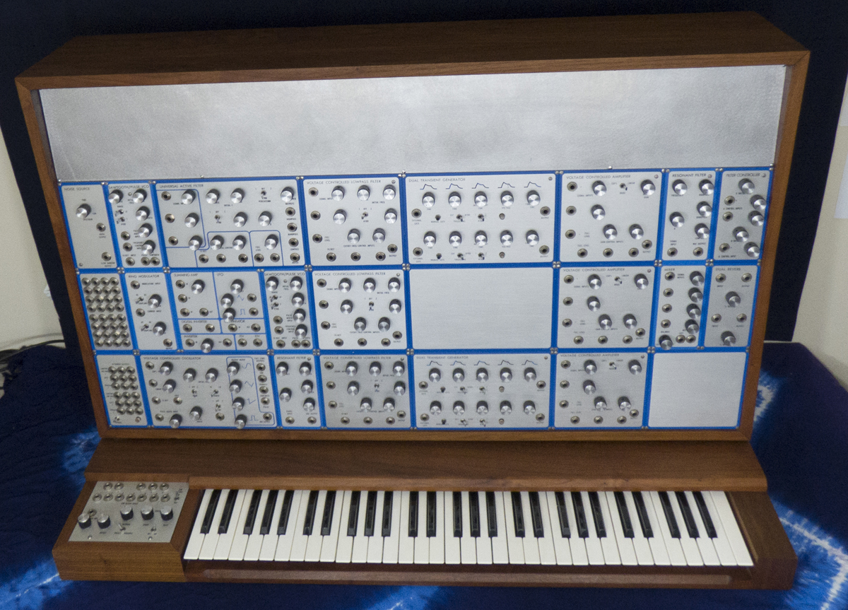
In order to see the amazing condition of this beautiful synthesizer I have taken photos of each module. On this page a close up photo of each module is shown.All pics have not been modified except for cropping and sizing. They were taken using daylight spectrum light bulbs. All pics in 300 ppi so will load slow on slower connections. Also, note due to some glare off the metal on individual module pictures, the silver background or text may look darker on some modules. Larger pictures show color better. >here All pictures taken at Mad Science Lab studio in April of 2017.List of all Modules, Going left to right, Row 1 firstModule 1 - Eµ MODULE 2400 - NOISE SOURCEModule 2 - Eµ MODULE 2210 - SAWTOOTH/PULSE VCOModule 3 - Eµ MODULE 2120 - UNIVERSAL ACTIVE FILTERModule 4 - Eµ MODULE 2100 - VOLTAGE CONTROLLED LOWPASS FILTERModule 5 - Eµ MODULE 2350 - DUAL DELAYED TRANSIENT GENERATORModule 6 - Eµ MODULE 2000 - VOLTAGE CONTROLLED AMPLIFIERModule 7 - Eµ MODULE 2140 - RESONANT FILTERModule 8 - Eµ MODULE 2145 - FILTER CONTROLLER---------- ROW 2 ---------------------Module 9 - Eµ MODULE 2906 - MULTIPLEModule 10 - Eµ MODULE 2430 - RING MODULATORModule 11 - Eµ MODULE 2451 - POTPOURRIModule 12 - Eµ MODULE 2210 - SAWTOOTH/PULSE VCOModule 13 - Eµ MODULE 2100 - VOLTAGE CONTROLLED LOWPASS FILTERModule 14 - Eµ MODULE 2000 - VOLTAGE CONTROLLED AMPLIFIERModule 15 - Eµ MODULE 2455 - MIXERModule 16 - Eµ MODULE 2460 - DUAL REVERB---------- ROW 3 ---------------------Module 17 - Eµ MODULE 2905 - POWER SUPPLYModule 18 - Eµ MODULE 2200 - VOLTAGE CONTROLLED OSCILLATORModule 19 - Eµ MODULE 2140 - RESONANT FILTERModule 20 - Eµ MODULE 2100 - VOLTAGE CONTROLLED LOWPASS FILTERModule 21 - Eµ MODULE 2350 - DUAL DELAYED TRANSIENT GENERATORModule 22 - Eµ MODULE 2000 - VOLTAGE CONTROLLED AMPLIFIER------------------------------------------------------------------------------------Close up photo of each Module3 rows of Modules, 22 modules total with 3 blank panels--------------- 1st Row ---- 8 Modules ----------------------------------------------------------- |
||||||||||||||||||||
 |
||||||||||||||||||||
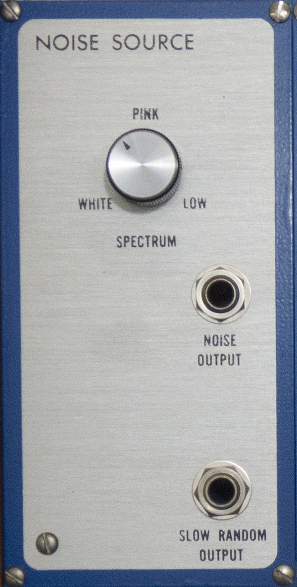
Module 1Eµ MODULE 2400 - NOISE SOURCEThe Eµ 2400 Noise Source produces random audio and control signals for use in electronic music. It contains an Eµ 1400 noise source submodule. The spectrum control varies the energy distribution of the audio output from white through pink to low filtered noise, by increasing the filtering on the original white noise signal from zero to 6 dB per octave. The slow random output gives a slowly varying control signal , whose energy is maximized in the range from 1 to 10 Hz. Due to the very low frequencies processed by this output, it will not become totally random for several seconds after power is applied. |
||||||||||||||||||||
 |
||||||||||||||||||||
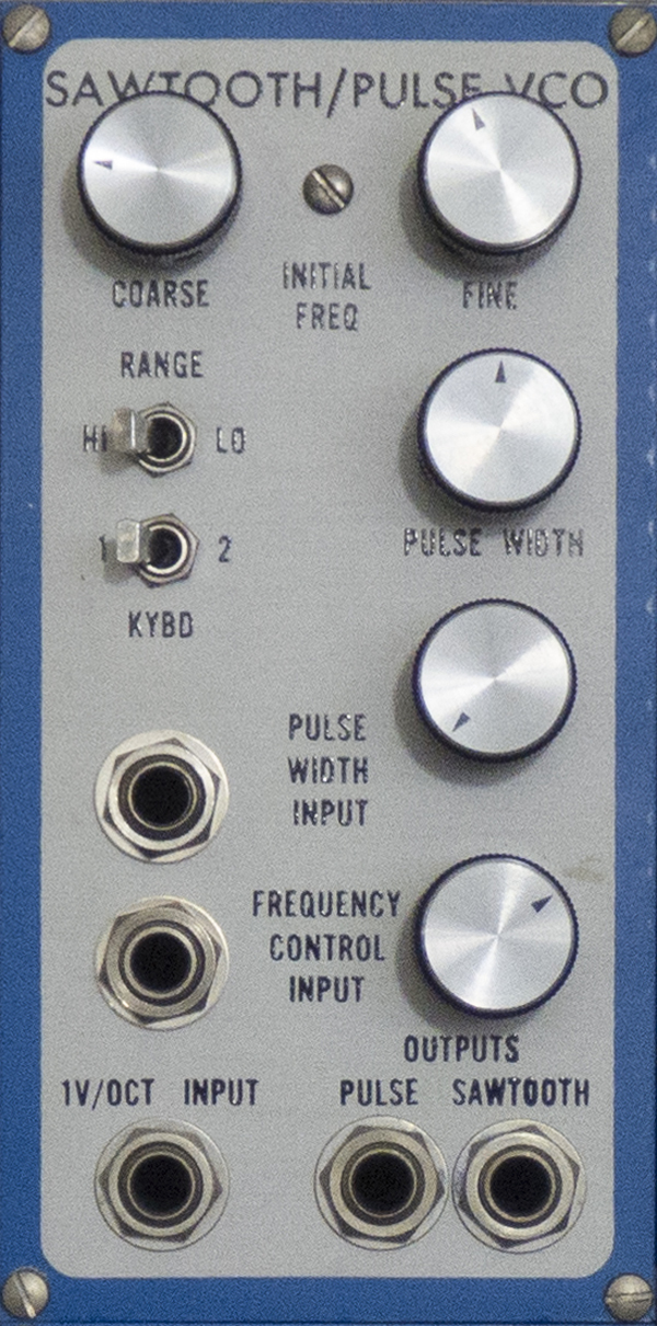
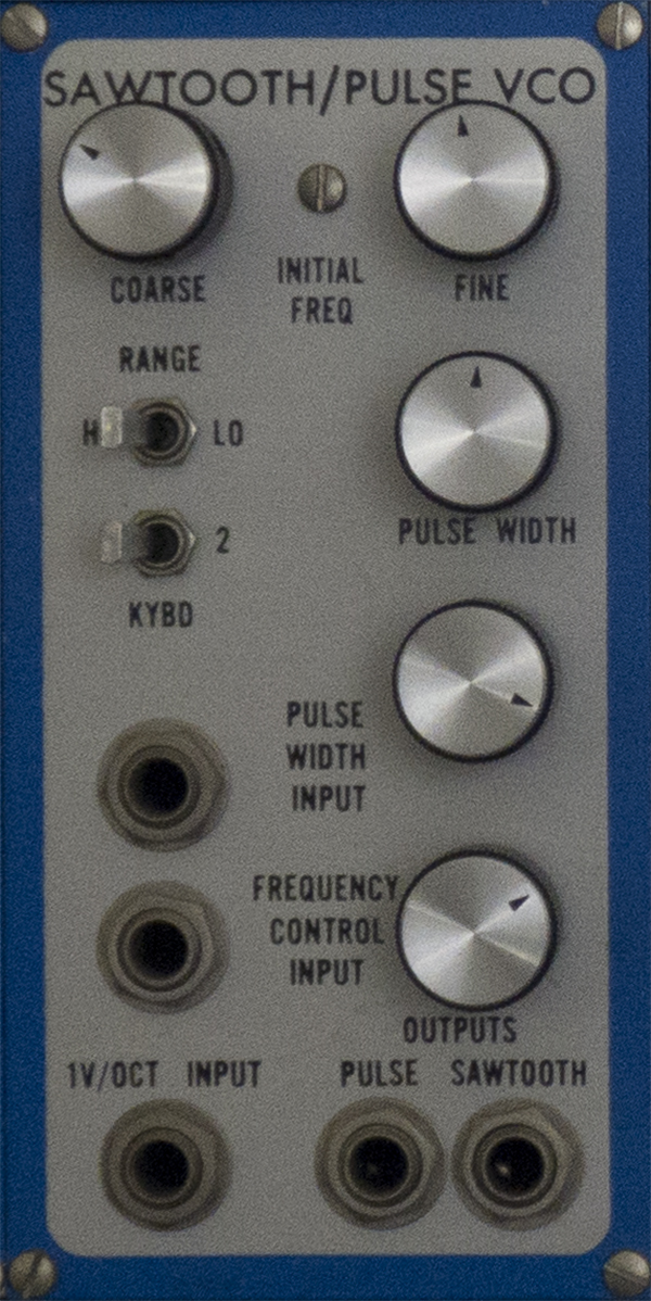
Module 2Eµ MODULE 2210 - SAWTOOTH/PULSE VCOThe Eµ 2210 Sawtooth/Pulse VCO is a two waveform exponentially voltage controlled oscillator with many of the features of our 2200 VCO. It contains the stable and accurate 1201 VCO submodule. The oscillator's frequency is determined by the sum of the settings of the coarse and fine initial frequency controls and any frequency control inputs. Control voltages may be applied from either of 2 keyboards via the keyboard switch, through the precision lV/octave input, or through the attenuated frequency control input. As with the 2200, switching to low range lowers the frequency ten octaves, but the entire 20 octave range may be continuously swept. The pulse width control and the pulse width modulation input are summed and vary the duty cycle of the pulse waveform from 0% to 100%, with a maximum sensitivity of 10%/volt. The phase relationship between sawtooth and pulse is the same as in the 2200: the pulse rises as the sawtooth falls, and the pulse falling edge location is controlled by pulse width modulation. |
||||||||||||||||||||
|
||||||||||||||||||||
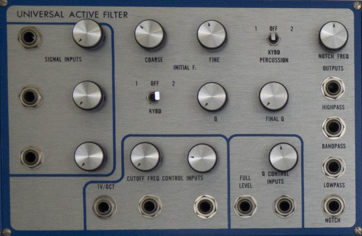
Module 3Eµ MODULE 2120 - UNIVERSAL ACTIVE FILTERThe Eµ 2120 Universal Active Filter is a fully voltage controlled filter with simultaneous highpass, bandpass, lowpass, and notch outputs. It contains an Eµ 1120 UAF submodule. Each of the three signal inputs passes through an attenuator, then the signals are summed and pass through the filter to appear at each of the outputs. The highpass signal is filtered 12 dB/octave below the cutoff frequency, the bandpass 6 dB/octave on both sides of cutoff, and the lowpass 12 dB/octave above cutoff. The notch output is unfiltered except for a 40 dB notch near the cutoff frequency. The Notch Frequency control will vary the ratio of the notch center frequency to the cutoff frequency several semitones to either side. The cutoff frequency is exponentially voltage controlled by the cutoff frequency inputs. The keyboard switch connects either of two keyboards at precisely lV/octave. The Q of this filter is exponentially voltage controlled over a range from 1/2 to 512, at one volt per factor of two change. The Q is numerically equal to the gain of the filter at the cutoff frequency. As Q is increased, the filter becomes extremely resonant at Fc. Up to 54 dB of gain can be achieved. The notch output is ineffective at high Q. With such high gains, it is very easy to cause the filter to distort. At high Q, the signal input attenuators should be set for low levels. The pass characteristics of the various outputs are as follows: With sufficiently high Q, fast signal transients such as pulse and sawtooth waveforms will cause the filter to "ring" at the cutoff frequency. The keyboard percussion switch patches a keyboard's gate and trigger signals into the filter to use this effect. On depression of a key, the trigger signal causes the filter to ring with a decay set by the Q control. When the key is released, the filter Q control instead becomes active, allowing a damping effect if desired. The final Q control has no effect with the keyboard percussion switch off.
|
||||||||||||||||||||
|
||||||||||||||||||||
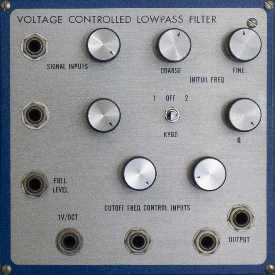
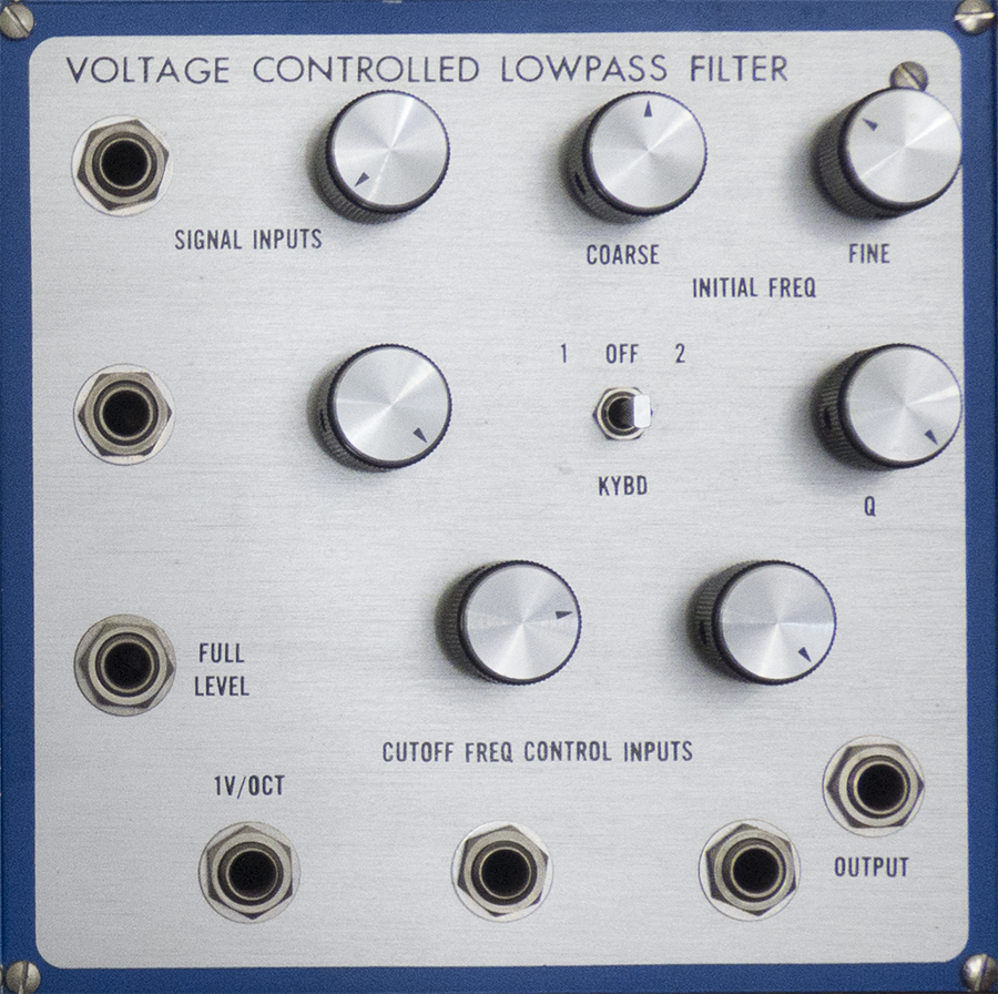
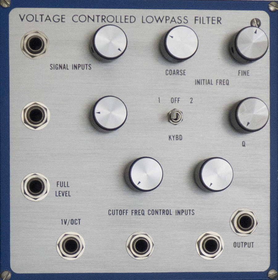
Module 4Eµ MODULE 2100 - VOLTAGE CONTROLLED LOWPASS FILTERThe Eµ 2100 Voltage Controlled Lowpass Filter is an exponentially controlled lowpass filter with variable Q for electronic music applications. It contains an Eµ 1100 VCF submodule. The top two signal inputs pass through their respective attenuators and are summed with the full level input to form the total signal input. This signal is then lowpass filtered with a cutoff frequency determined by the sum of the initial cutoff frequency controls and the control inputs. The cutoff slope is 24 dB/octave, and the signal path is DC coupled. The control inputs are algebraically summed to give a total control input voltage, which will vary the cutoff frequency one octave per volt around the initial cutoff frequency. The keyboard switch allows instant patching of either of two keyboards at precisely one volt per octave. The 1V/octave control input jack is also accurately calibrated. Although maximum accuracy is maintained over the range of 20Hz - 20KHz, the cutoff frequency may be brought as low as 1Hz for special effects. The Q control varies the resonance of the filter at the cutoff frequency. As the Q approaches maximum setting, the filter breaks into oscillation, producing a pure sine wave. Lowest distortion occurs with the Q control set barely into the oscillation region.
|
||||||||||||||||||||
|
||||||||||||||||||||
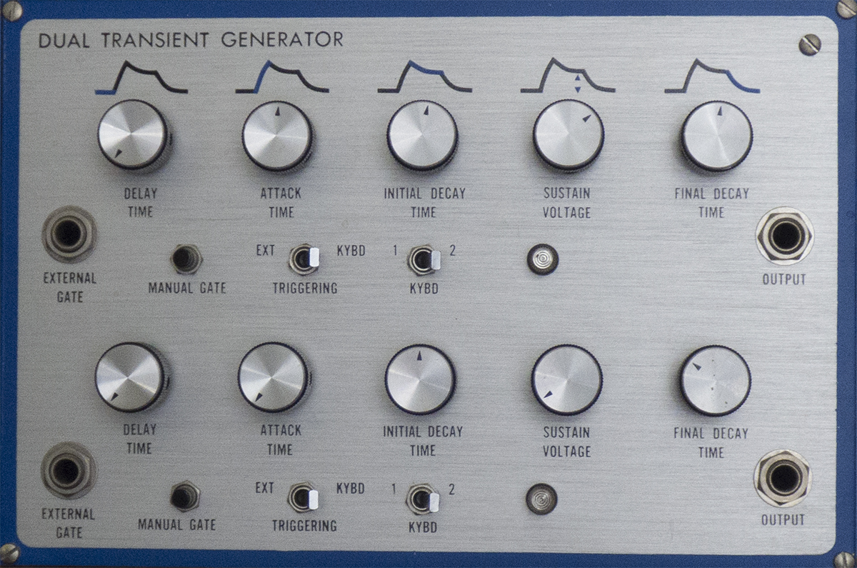
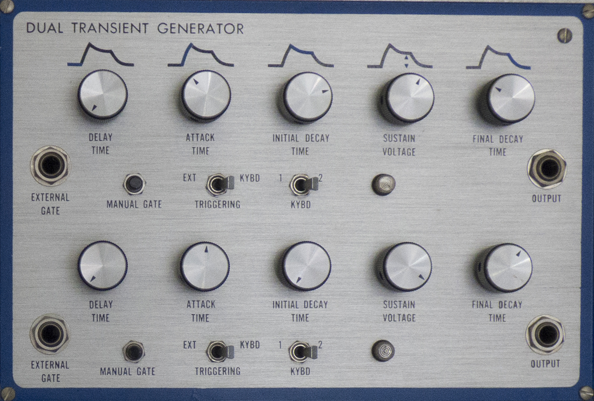
Module 5Eµ MODULE 2350 - DUAL DELAYED TRANSIENT GENERATORThe Eµ 2350 Dual Delayed Transient Generator module contains two independent four-phase electronic music transient generators in a single module. It is based on two Eµ 1350 submodules. With the triggering switch in the external position, the module will produce a four-phase transient when triggered by an external gate: The time constants for the four independent phases, and the sustain voltage, are determined by the settings of the appropriate controls. In the keyboard mode, the module will similarly respond to the depression of a key (producing simultaneous gate and trigger) with a delay, attack, initial decay, and final decay. Should an additional key be depressed before the first is released, a new attack will begin after the delay time has elapsed. When all keys are released, final decay phase always begins, and no further attacks will occur. If the delay function is not desired, the delay control should be set fully counterclockwise. The manual gate acts in the same manner as an external gate input, allowing the user to conveniently determine the effect of a particular transient generator section within a complex patch. The attack, initial decay, and final decay contours are all exponential functions in time, whose time constants are variable over a wide range. The controls vary the time constants exponentially, resulting in remarkably smooth and accurate control over the entire range. The standard control range for the time constants is 1 millisecond to 10 seconds (3 msec to 3 seconds on delay), but the range can be expanded or reduced on request. The gate lamp indicates the presence of a high level (logic "l") on the gate input. |
||||||||||||||||||||
 |
||||||||||||||||||||
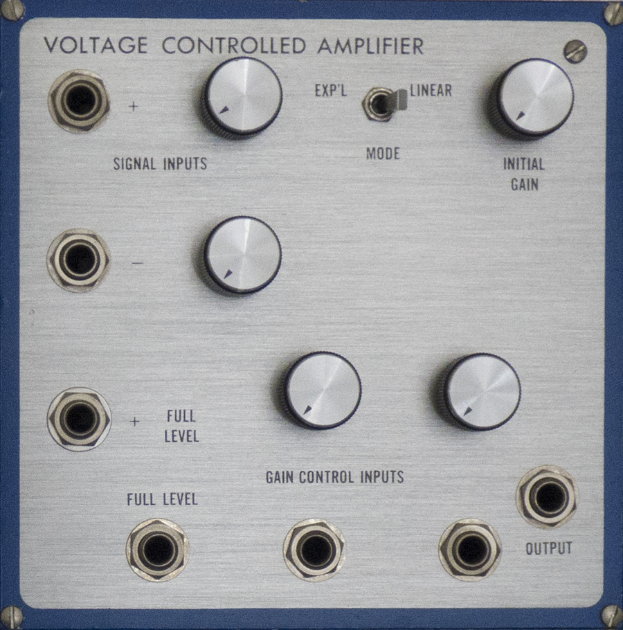
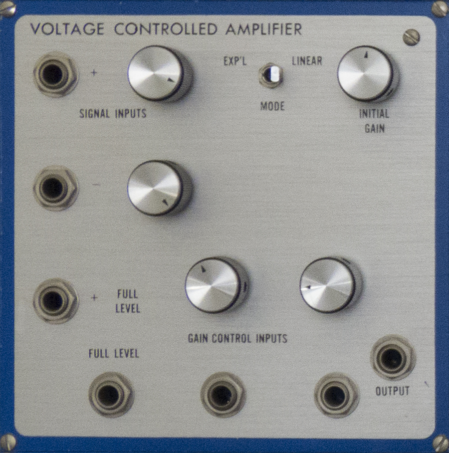
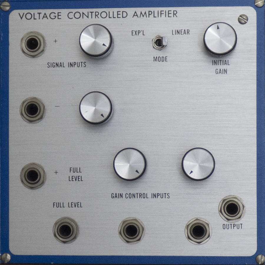
Module 6Eµ MODULE 2000 - VOLTAGE CONTROLLED AMPLIFIERThe Eµ 2000 Voltage Controlled Amplifier is an exponentially and/or linearly controlled amplifier for envelope shaping or control functions. It contains an Eµ 1001 VCA submodule. The top two signal inputs pass through their respective attenuators, and are summed with the full level input. The result appears at the output, amplified by a factor determined by the control inputs. The second signal input is inverting for increased flexibility. The control inputs are similarly summed with the initial gain control (which effectively varies from -5 to +5 volts) to produce the total input control voltage. The 3 position mode switch determines the function of the control voltages. In linear mode, the amplifier has zero gain for total control voltages below zero, and the gain increases linearly above zero, passing through unity at +5 volts. In exponential mode, the amplifier again has unity gain at +5 volts, and changes 10 dB per volt around this point. With the mode switch in the center position, the two leftmost control inputs and the initial gain control behave the same as in linear mode. The rightmost control input, however, acts as a multiplier on the gain, with a sensitivity of 10 dB per volt. Maximum gain available from the amplifier is approximately +6 dB. |
||||||||||||||||||||
|
||||||||||||||||||||
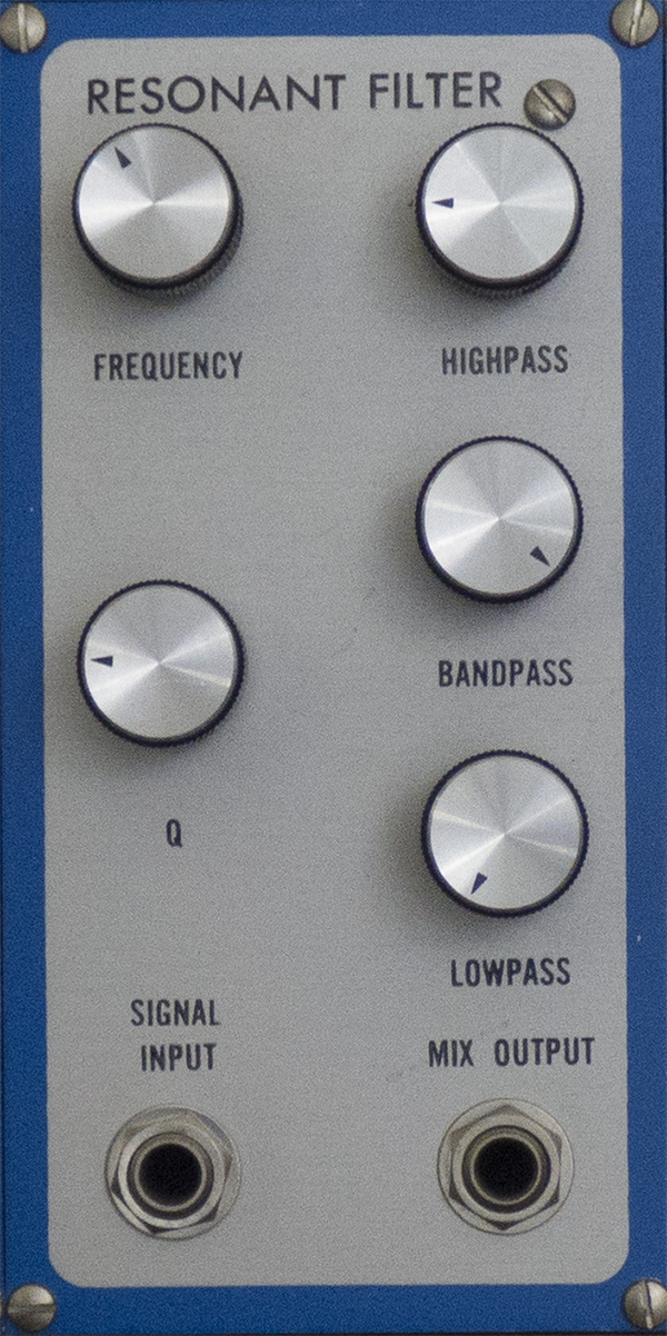
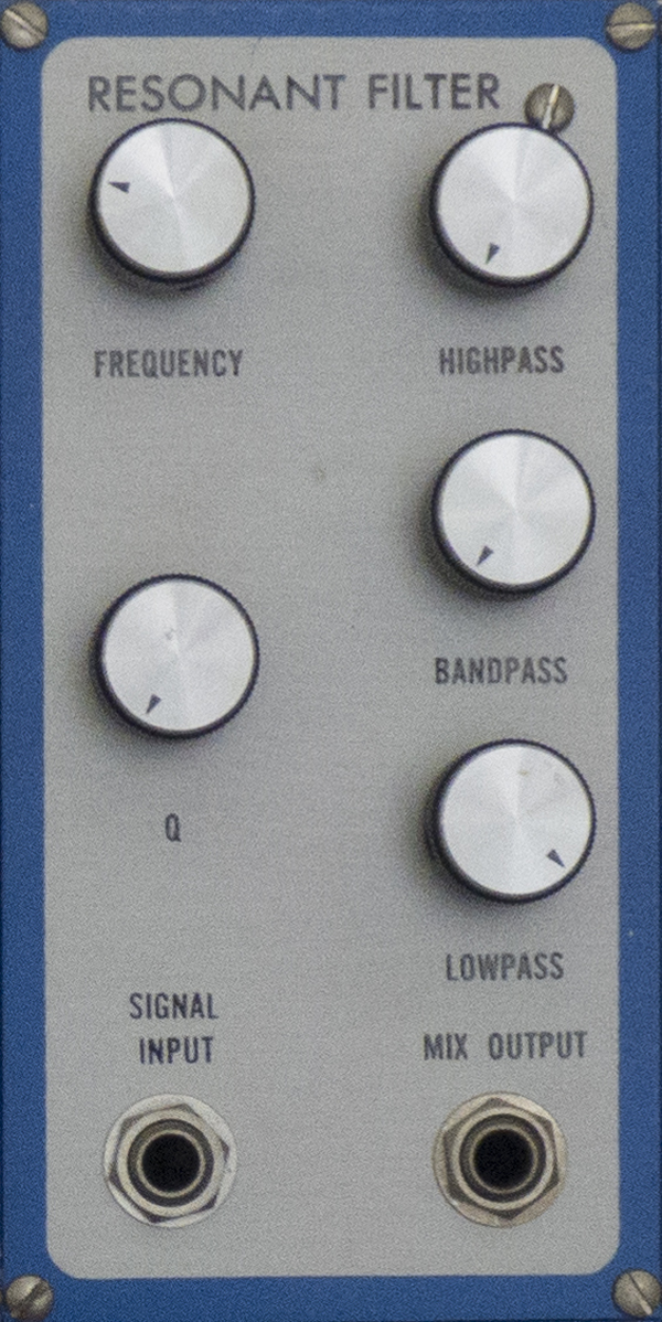
Module 7Eµ MODULE 2140 - RESONANT FILTERThe Eµ 2140 Resonant Filter is an audio filter with an output mixer capable of producing virtually any two pole pass characteristic. It contains an Eµ 1140 Audio UAF submodule. The setting of the frequency control determines the filter center frequency, which can be varied from 20 Hz to 20KHz. A resonant peak may be added to the response by the Q control. The height of this peak is variable from zero to ˜ +40 dB. The output mixer sums the simultaneous filter functions to produce a single output. An incredibly wide variety of responses can be produced, a few of which are shown below. Several 2140's can be cascaded in series/ parallel combinations to produce interesting complex resonant formants. Lower input levels should be used at high Q's to prevent clipping. This module is also controlled by module 8, the Eµ MODULE 2145 - FILTER CONTROLLER
|
||||||||||||||||||||
|
||||||||||||||||||||
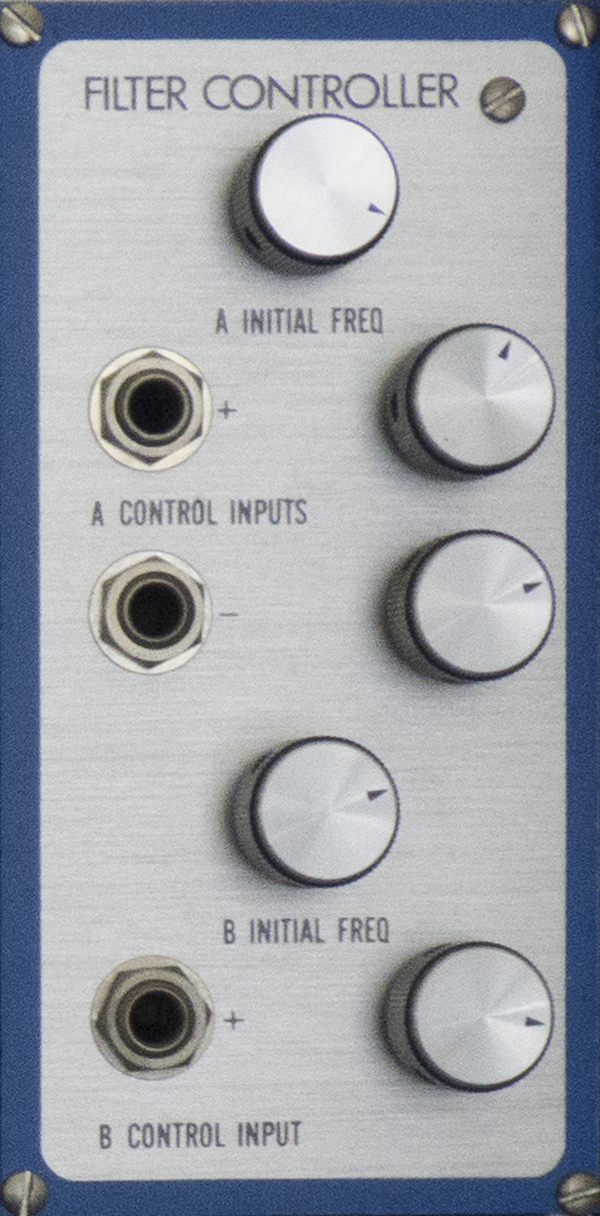
Module 8Eµ MODULE 2145 - FILTER CONTROLLERThe Eµ 2145 Filter Controller allows voltage control of the frequency of two banks of Eµ 2140 Resonant Filters. Each bank of filters may contain from one to four 2140 units connected in any series or parallel combination. The bank center frequency will be determined by the 2145 controller while the formant shape will remain unchanged. The "A" section initial frequency control alters the frequency of the "A" filter bank by +5 octaves. The "A" section "+" control input will shift the frequency of the "A" bank with a maximum sensitivity of 1 volt/octave, depending on the setting of the adjacent attenuator. The "-" control input will similarly shift the "A" bank, but will respond to a positive voltage with a negative frequency shift. The "B" filter bank is similarly controlled by the "B" section initial frequency control and the "+" control input. When no external patch is made to the "-" control input in the "A" section, this is pre-patched to the control output for the "B" section. Hence, with the attenuator turned up, rotation of the "B" section initial frequency control, or applying a voltage to the "B" section "+" control input will shift the "B" bank up in frequency while shifting the "A" bank down, an interesting stereo musical effect. NOTE: On this E-mu Modular the A control is for the Module 7 Eµ 2140 Resonant Filter frequency, and the B control is for Module 19 Eµ 2140 Resonant Filter frequency |
||||||||||||||||||||
--------------- 2nd Row ----- 8 Modules ------------------------------------------------------------- |
||||||||||||||||||||
 |
||||||||||||||||||||
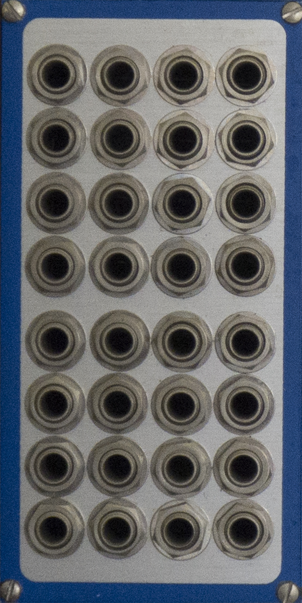
Module 9Eµ MODULE 2906 - MULTIPLEThe Eµ 2906 multiple panel consists of eight four-wide multiples. All 4 jacks in each row are connected together. |
||||||||||||||||||||
 |
||||||||||||||||||||
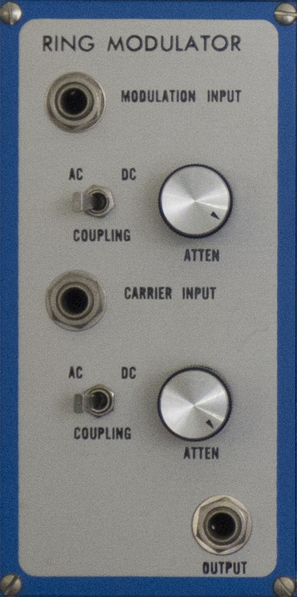
Module 10Eµ MODULE 2430 - RING MODULATORThe Eµ 2430 Ring Modulator is a balanced modulator for electronic music. It contains an Eµ 1430 ring modulator submodule. The module has two inputs, modulation and carrier, which are identical for high signal levels. The output is the algebraic product of the input voltages: Vout = Vmod x Vcar ÷ 5 when the input attenuators are fully clockwise and the coupling switches are in the DC position. AC coupling will level-shift the corresponding input so it effectively centers around zero volts. This can have a striking effect on the output signal, due to the inherent non-linearity of balanced modulation. The Eµ 2430 was designed for high carrier rejection in the absence of a modulation signal, typically in excess of 80dB. The reverse rejection, that of modulation feedthrough with no carrier, is only 40dB. |
||||||||||||||||||||
 |
||||||||||||||||||||
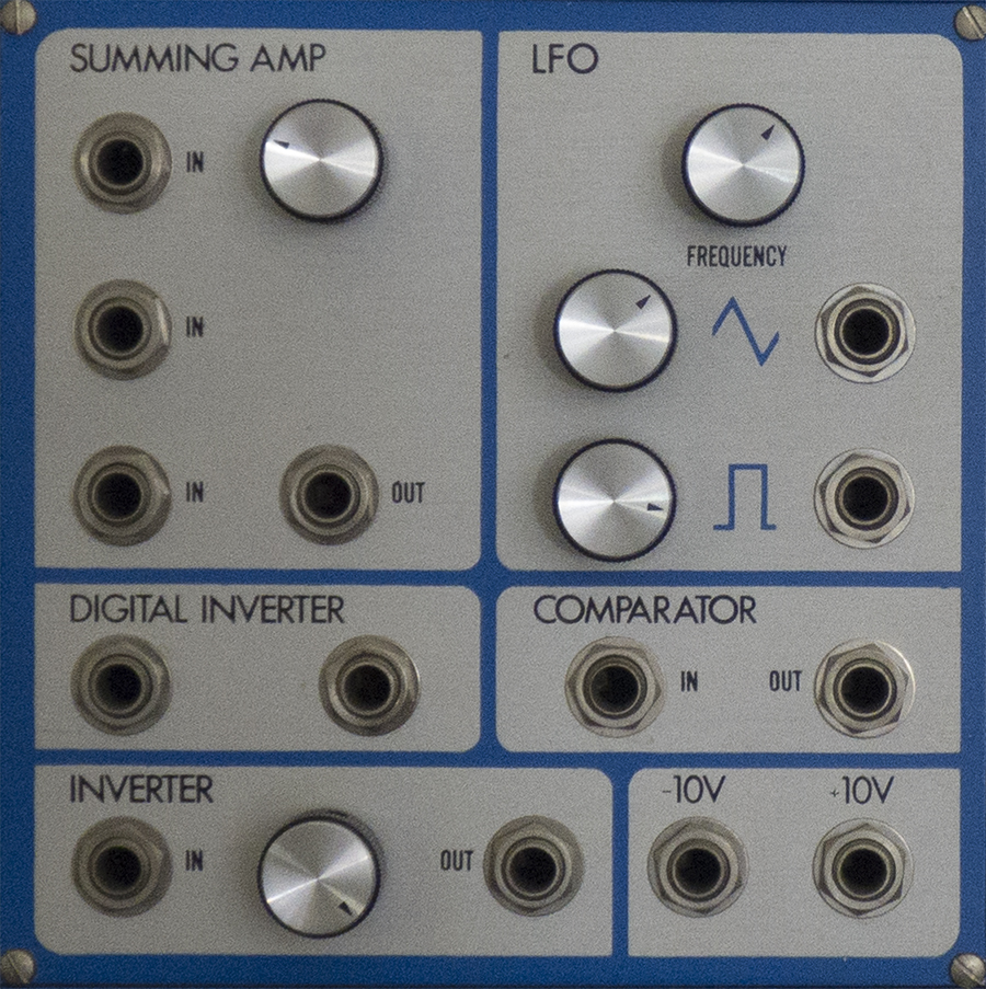
Module 11Eµ MODULE 2451 - POTPOURRIThe Eµ 2451 Potpourri Module is a multipurpose module designed to add a variety of useful functions to small or medium sized modular systems. The output voltage of the Summing Amp is precisely the sum of the upper input voltage as attenuated by the adjacent control, plus the voltages at the second and third input jacks. The Digital Inverter produces a logic "O" (low impedance to ground) if the input voltage is greater than 3.5 volts, and produces a logic "1" (l.OK? to +5 volts) if the input is less than 1.5 volts. Thus the output is the logical inversion of the input. The output voltage of the Inverter section is the negative (+1 volt in gives -l volt out) of the input, as attenuated by the adjacent control. The LFO is a low frequency oscillator giving triangle and square wave outputs with amplitudes adjustable by the adjacent controls. The oscillation frequency is adjustable from 0.02 to 50 Hz. The Comparator produces a digital output that will be a logic "1" if the input voltage is greater than 0.25 volts, and a logic "0" for inputs below 0.1 volts. Some hysteresis is provided to prevent oscillation even on very slowly changing inputs. The +lOV and -lOV jacks give these voltages with an impedance of l.OK.
|
||||||||||||||||||||
 |
||||||||||||||||||||
Module 12Eµ MODULE 2210 - SAWTOOTH/PULSE VCOThe Eµ 2210 Sawtooth/Pulse VCO is a two waveform exponentially voltage controlled oscillator with many of the features of our 2200 VCO. It contains the stable and accurate 1201 VCO submodule. The oscillator's frequency is determined by the sum of the settings of the coarse and fine initial frequency controls and any frequency control inputs. Control voltages may be applied from either of 2 keyboards via the keyboard switch, through the precision lV/octave input, or through the attenuated frequency control input. As with the 2200, switching to low range lowers the frequency ten octaves, but the entire 20 octave range may be continuously swept. The pulse width control and the pulse width modulation input are summed and vary the duty cycle of the pulse waveform from 0% to 100%, with a maximum sensitivity of 10%/volt. The phase relationship between sawtooth and pulse is the same as in the 2200: the pulse rises as the sawtooth falls, and the pulse falling edge location is controlled by pulse width modulation.
|
||||||||||||||||||||
 |
||||||||||||||||||||
Module 13Eµ MODULE 2100 - VOLTAGE CONTROLLED LOWPASS FILTERThe Eµ 2100 Voltage Controlled Lowpass Filter is an exponentially controlled lowpass filter with variable Q for electronic music applications. It contains an Eµ 1100 VCF submodule. The top two signal inputs pass through their respective attenuators and are summed with the full level input to form the total signal input. This signal is then lowpass filtered with a cutoff frequency determined by the sum of the initial cutoff frequency controls and the control inputs. The cutoff slope is 24 dB/octave, and the signal path is DC coupled. The control inputs are algebraically summed to give a total control input voltage, which will vary the cutoff frequency one octave per volt around the initial cutoff frequency. The keyboard switch allows instant patching of either of two keyboards at precisely one volt per octave. The 1V/octave control input jack is also accurately calibrated. Although maximum accuracy is maintained over the range of 20Hz - 20KHz, the cutoff frequency may be brought as low as 1Hz for special effects. The Q control varies the resonance of the filter at the cutoff frequency. As the Q approaches maximum setting, the filter breaks into oscillation, producing a pure sine wave. Lowest distortion occurs with the Q control set barely into the oscillation region.
|
||||||||||||||||||||
| Large Blank panel, expansion room | ||||||||||||||||||||
 |
||||||||||||||||||||
Module 14Eµ MODULE 2000 - VOLTAGE CONTROLLED AMPLIFIERThe Eµ 2000 Voltage Controlled Amplifier is an exponentially and/or linearly controlled amplifier for envelope shaping or control functions. It contains an Eµ 1001 VCA submodule. The top two signal inputs pass through their respective attenuators, and are summed with the full level input. The result appears at the output, amplified by a factor determined by the control inputs. The second signal input is inverting for increased flexibility. The control inputs are similarly summed with the initial gain control (which effectively varies from -5 to +5 volts) to produce the total input control voltage. The 3 position mode switch determines the function of the control voltages. In linear mode, the amplifier has zero gain for total control voltages below zero, and the gain increases linearly above zero, passing through unity at +5 volts. In exponential mode, the amplifier again has unity gain at +5 volts, and changes 10 dB per volt around this point. With the mode switch in the center position, the two left most control inputs and the initial gain control behave the same as in linear mode. The right most control input, however, acts as a multiplier on the gain, with a sensitivity of 10 dB per volt. Maximum gain available from the amplifier is approximately +6 dB. |
||||||||||||||||||||
 |
||||||||||||||||||||
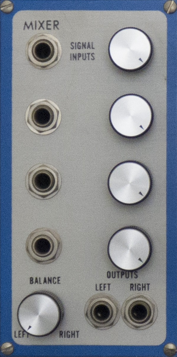
Module 15Eµ MODULE 2455 - MIXERThe Eµ 2455 Mixer is a four input, stereo output mixer with pan for use within the Eµ modular system. While a mixer is seldom needed in the system as most modules provide input mixing (multiple inputs with attenuators) and output mixing (patching several outputs together in a multiple gives an even mix of the outputs), a dedicated mixer module may prove useful in special situations. The four signal inputs pass through their respective attenuators and are summed to give the mixer output signal. This is then routed into the left and right outputs in a ratio determined by the setting of the balance control. With the balance control fully counterclockwise, the output signal appears unattenuated at the left output jack and no signal appears at the right jack; with the control clockwise, the entire signal is routed instead to the right output jack. At intermediate settings, an appropriate signal level is sent to each jack to simulate spatial positioning, with the total power from the two jacks remaining constant. The balance control could thus be used as a master volume control if only one output were used. |
||||||||||||||||||||
 |
||||||||||||||||||||
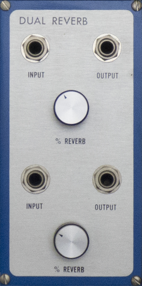
Module 16Eµ MODULE 2460 - DUAL REVERBThe Eµ 2460 Dual Reverb module is a dual spring type reverberation unit, using an Eµ 1420 submodule. The two channels are completely independent. The input signal to a channel is AC coupled and sent to the reverb spring. The return signal is amplified, and then mixed with the original AC coupled signal, according to the setting of the "% Reverb" control, to produce the final output. The reverb elements are physically separate from the module, and it is recommended that they be placed remote to the synthesizer cabinet to minimize the effects of vibration and hum. If these precautions are taken, the noise and hum are virtually inaudible in normal use.
|
||||||||||||||||||||
--------------- 3rd Row ------- 6 modules --------------------------------------------------------- |
||||||||||||||||||||
 |
||||||||||||||||||||
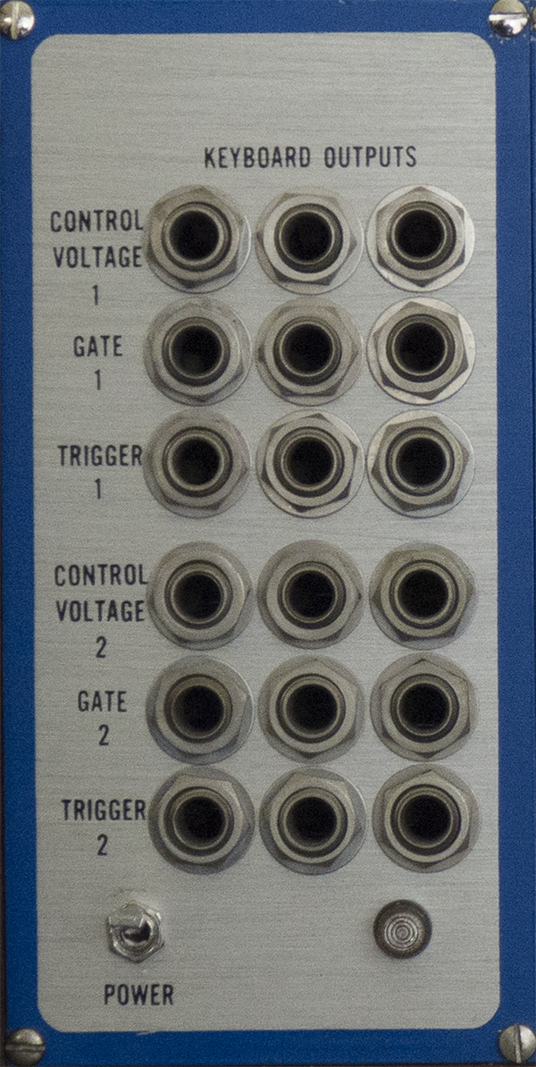
Module 17Eµ MODULE 2905 - POWER SUPPLYThe Eµ 2905 Power Supply Modules are complete power systems for Eµ modular synthesizers. The 2905's front panel contains the power switch and pilot lamp, plus multiple outputs for two keyboards. When a keyboard is not connected, the associated system busses can be used for routing any signal by applying via these power supply panel jacks. The interface panel (on cabinet rear) holds the power cord connector, fuse, and connectors for the two keyboards. In addition, four general purpose 24 pin connectors are provided. These can be used for custom functions, multi-voiced keyboard connections, or inter-cabinet firm-wiring. The power supplies are current limited, overvoltage and reverse voltage protected, and factory calibrated. One 2905 module is required per cabinet. Additional Note: If you want to control the gates with an external trigger you need to connect both the trigger and gate. The easiest way is to plug a jumper cable between the trigger and gate jacks, and then plug your external signal into the gate. This is because the envelopes can be triggered in many different ways. See the Dual transient generator information
|
||||||||||||||||||||
 |
||||||||||||||||||||
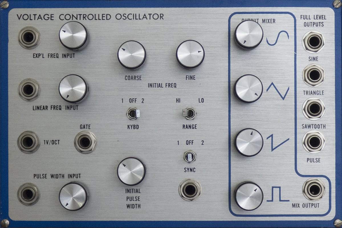
Module 18Eµ MODULE 2200 - VOLTAGE CONTROLLED OSCILLATORThe Eµ 2200 Voltage Controlled Oscillator is a complete, four waveform, exponentially and linearly controlled oscillator with an output mixer. It is exceptionally stable and accurate for use with full size synthesizer keyboards. It contains an Eµ 1201 VCO submodule, and an Eµ 1210 wave converter submodule. The upper three inputs are for frequency control. The uppermost is attenuable from 1 volt per octave with exponential response; the center has AC coupled linear response with a maximum sensitivity of 20% per volt. The lowest input responds exponentially at precisely lV/octave. The keyboard switch will instantly connect either of two keyboards at exactly lV/octave. The oscillator's initial frequency can be adjusted by the coarse control over more than ten octaves, while the fine adjustment with its four semitone range allows precise tuning. The range switch shifts the oscillator initial frequency down ten octaves. The frequency can be swept, however, over the entire twenty octave range from 0.03Hz to 30KHz. The pulse width control and the pulse width modulation input vary the duty cycle of the pulse waveform from 0% to 100%. Maximum sensitivity is 10%/volt. The four upper output jacks give each of the waveforms at full level (lOV peak-to-peak for sine, triangle, and pulse, 0 to +5V for sawtooth). The waveforms are phased as shown on the panel; the falling edge of the pulse waveform is varied by the pulse width voltage. The output mixer enables the creation of waveforms with infinitely variable harmonic content. The mixer is inverting, allowing the oscillator to simultaneously produce any output waveform and its inverse for control purposes. The sync switch allows phase-locking any oscillators in the system. Oscillators tuned to whole number ratios will lock if their sync switches connect them to the same sync bus. The range of pull is slightly less than a semi tone. The sync input will force the sawtooth to discharge, taking the other waveforms to their analogous locations, when a rapidly falling edge is applied. The gate input synchronously turns the oscillator off when the input exceeds about +2.5V. As long as the high level is maintained, the sawtooth is not allowed to discharge, and rests slightly above +5 volts. As soon as the gate input is brought low, the discharge occurs, and the oscillator runs again. The gating and sync input features are not only useful in control oscillators at subaudio frequencies, but also produce interesting timbres when both the controlling and sync'd or gated oscillators are run at audio rates.
|
||||||||||||||||||||
 |
||||||||||||||||||||
Module 19Eµ MODULE 2140 - RESONANT FILTERThe Eµ 2140 Resonant Filter is an audio filter with an output mixer capable of producing virtually any two pole pass characteristic. It contains an Eµ 1140 Audio UAF submodule. The setting of the frequency control determines the filter center frequency, which can be varied from 20 Hz to 20KHz. A resonant peak may be added to the response by the Q control. The height of this peak is variable from zero to ˜ +40 dB. The output mixer sums the simultaneous filter functions to produce a single output. An incredibly wide variety of responses can be produced, a few of which are shown below. Several 2140's can be cascaded in series/ parallel combinations to produce interesting complex resonant formants. Lower input levels should be used at high Q's to prevent clipping. This module is also controlled by module 8, the Eµ MODULE 2145 - FILTER CONTROLLER
|
||||||||||||||||||||
 |
||||||||||||||||||||
Module 20Eµ MODULE 2100 - VOLTAGE CONTROLLED LOWPASS FILTERThe Eµ 2100 Voltage Controlled Lowpass Filter is an exponentially controlled lowpass filter with variable Q for electronic music applications. It contains an Eµ 1100 VCF submodule. The top two signal inputs pass through their respective attenuators and are summed with the full level input to form the total signal input. This signal is then lowpass filtered with a cutoff frequency determined by the sum of the initial cutoff frequency controls and the control inputs. The cutoff slope is 24 dB/octave, and the signal path is DC coupled. The control inputs are algebraically summed to give a total control input voltage, which will vary the cutoff frequency one octave per volt around the initial cutoff frequency. The keyboard switch allows instant patching of either of two keyboards at precisely one volt per octave. The 1V/octave control input jack is also accurately calibrated. Although maximum accuracy is maintained over the range of 20Hz - 20KHz, the cutoff frequency may be brought as low as 1Hz for special effects. The Q control varies the resonance of the filter at the cutoff frequency. As the Q approaches maximum setting, the filter breaks into oscillation, producing a pure sine wave. Lowest distortion occurs with the Q control set barely into the oscillation region.
|
||||||||||||||||||||
 |
||||||||||||||||||||
Module 21Eµ MODULE 2350 - DUAL DELAYED TRANSIENT GENERATORThe Eµ 2350 Dual Delayed Transient Generator module contains two independent four-phase electronic music transient generators in a single module. It is based on two Eµ 1350 submodules. With the triggering switch in the external position, the module will produce a four-phase transient when triggered by an external gate: The time constants for the four independent phases, and the sustain voltage, are determined by the settings of the appropriate controls. In the keyboard mode, the module will similarly respond to the depression of a key (producing simultaneous gate and trigger) with a delay, attack, initial decay, and final decay. Should an additional key be depressed before the first is released, a new attack will begin after the delay time has elapsed. When all keys are released, final decay phase always begins, and no further attacks will occur. If the delay function is not desired, the delay control should be set fully counterclockwise. The manual gate acts in the same manner as an external gate input, allowing the user to conveniently determine the effect of a particular transient generator section within a complex patch. The attack, initial decay, and final decay contours are all exponential functions in time, whose time constants are variable over a wide range. The controls vary the time constants exponentially, resulting in remarkably smooth and accurate control over the entire range. The standard control range for the time constants is 1 millisecond to 10 seconds (3 msec to 3 seconds on delay), but the range can be expanded or reduced on request. The gate lamp indicates the presence of a high level (logic "l") on the gate input. |
||||||||||||||||||||
 |
||||||||||||||||||||
Module 22Eµ MODULE 2000 - VOLTAGE CONTROLLED AMPLIFIERThe Eµ 2000 Voltage Controlled Amplifier is an exponentially and/or linearly controlled amplifier for envelope shaping or control functions. It contains an Eµ 1001 VCA submodule. The top two signal inputs pass through their respective attenuators, and are summed with the full level input. The result appears at the output, amplified by a factor determined by the control inputs. The second signal input is inverting for increased flexibility. The control inputs are similarly summed with the initial gain control (which effectively varies from -5 to +5 volts) to produce the total input control voltage. The 3 position mode switch determines the function of the control voltages. In linear mode, the amplifier has zero gain for total control voltages below zero, and the gain increases linearly above zero, passing through unity at +5 volts. In exponential mode, the amplifier again has unity gain at +5 volts, and changes 10 dB per volt around this point. With the mode switch in the center position, the two left most control inputs and the initial gain control behave the same as in linear mode. The right most control input, however, acts as a multiplier on the gain, with a sensitivity of 10 dB per volt. Maximum gain available from the amplifier is approximately +6 dB. |
||||||||||||||||||||
Blank Panel, ready for expansion |
||||||||||||||||||||
Back to E-mu Modular 2017 Main Page |
Silicon Breakdown has been a source of free information and pictures for analog synthesizers since 1999
The Music side of this site contains the sounds of Silicon Breakdown and various other musical adventures. MUSIC HERE
The Synth side showcases beautiful instruments from the past. ANALOG SYNTHESIZER INFO HERE
send comments to james AT siliconbreakdown.com (replace AT with @)